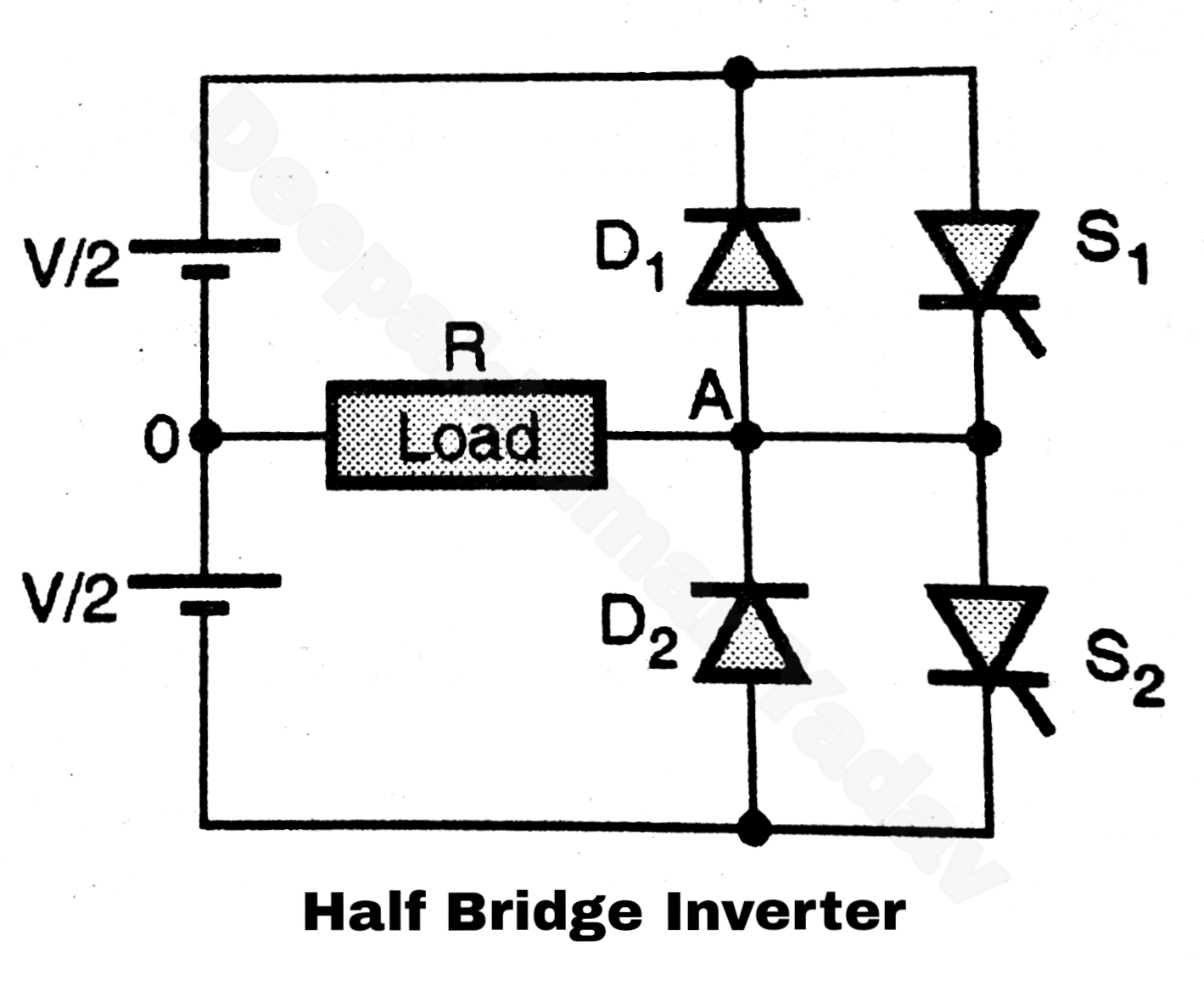
Single phase half bridge inverter Half bridge power circuit photos and images A clever voltage-fed half-bridge converter architecture
Schematic representation of the MOSFET-based half-bridge circuit
(a) schematic of the half bridge used in the experimental setup. (b
Schematic diagram of half bridge converter circuit
Half converter schematicSmps ir2153 document Schematic of half-bridge converter with split dc supply.Half-bridge isolated dc-dc converter design.
Half-bridge topology finds applications in high density powerSchematic diagram of proposed single-phase half-bridge dstatcom Pwm mosfet 4qdA) circuit schematic of the half bridge llc converter b) conceptual.

Tahmid's blog: smps topomagic
Inductive schematic principleHalf bridge driver based on ir2104 Figure-2-schematic-of-one-half-bridgeTopology converters schematic.
Schematic mmcHalf bridge converter electrical schematic diagram Half-bridge circuit schematic.Half bridge smps circuit diagram.

Bridge driver half ir2104 schematic based pwm electronics lab single supply input
Half bridge inverterHalf-bridge drivers Schematic of the half-bridge mmc.Half bridge.
Half bridge [tour 6]Half bridge configuration. Half converter split schematicExplanation of half bridge.

(pdf) an introduction to llc resonant half-bridge converters
Bridge half structureBridge half Smps half bridge ir2153 2.0Single phase half bridge inverter.
Schematic representation of the mosfet-based half-bridge circuitLmg3411r050: is there a way to reset fault pin? Bridge voltage converter electronicdesign powerelectronicsBridge half motor schematic figure rear.

Principle schematic of a half bridge driving an inductive load
Circuit infineon diagramm exportHalf-bridge schematic Full bridge smps circuit diagramBridge smps circuit half full software enlarge let use click tahmid.
.


